CIRCUIT BREAKER BUYER GUIDE
Circuit Breaker B C and D Curves Why Starting Current Changes the Choice
Share on social media
Why a breaker’s trip curve must match both starting behaviour and fault protection, and why moving from B to C or D is not a safe shortcut for stopping nuisance trips.
A trip at startup is a symptom, not a selection rule
A pump starts and the breaker opens. Replacing it with a D-curve device may sound like an easy solution, but stopping the trip is only half the task. The circuit must still disconnect faults safely. For Pakistani homes and businesses combining solar, backup power and motor loads, selection needs the load’s starting behaviour and the electrical protection design—not a rule that one letter is always better.
Schneider Electric’s guidance distinguishes loads with low starting current from inductive or capacitive loads with larger inrush. Motors are one example, but electronic loads can also create short current peaks. The peak’s duration matters as well as its size: the installer needs the equipment data or appropriate measurements, not just its normal running watts. [2]
What B, C and D actually describe
A thermal-magnetic miniature circuit breaker has a time-dependent overload region and a rapid magnetic-trip region. The B, C or D characteristic primarily distinguishes the latter. ABB’s published IEC/EN 60898 AC curves show B at 3–5 times rated current, C at 5–10 times and D at 10–20 times. Rated current is commonly written as In. [1]
These bands are not permitted continuous-load multipliers. Nor does the lower boundary mean every device instantly trips at precisely that value. They belong to defined test conditions and a time–current characteristic. Use the manufacturer’s complete curve, including tolerances, rather than reading a letter as a standalone guarantee. A D curve does not turn an overloaded cable into a suitably protected cable. [1]
Keep IEC 60898 and IEC 60947 information separate
Do not assume the same letter always gives an identical band across different product standards. Schneider’s published guidance, for example, describes D/K magnetic operation at 10–14 times rated current for its referenced IEC 60947-2 devices. That is not a universal replacement for the IEC/EN 60898 D band of 10–20. The manufacturer, product family, applicable standard and actual published characteristic must travel together. [2]
For purchasing, request the complete product reference and curve sheet. A generic online chart is not enough to establish the suitability of the breaker offered. This guide’s AC curve discussion is also not a specification for the DC side of a PV or battery system.
Higher inrush tolerance has a fault-clearance trade-off
In a TN earthing arrangement, excessive fault-loop impedance can limit earth-fault current so that an overcurrent device does not disconnect within the required time. Schneider’s Electrical Installation Guide explains this problem and discusses lower magnetic thresholds among possible engineered responses. The important buying lesson is the reverse too: raising the magnetic threshold cannot be approved solely because it stops startup trips. [3]
Ask the designer to verify the applicable disconnection requirements against the actual earthing arrangement, conductor system, available fault current and chosen device. Do not copy a maximum cable length or loop-impedance limit from an unrelated installation. Those checks require a qualified electrical professional and appropriate test equipment.
Solar backup needs its own operating-mode check
The source feeding a circuit matters. As a product-specific example, Victron’s SUN Inverter manual describes a fast-acting current limiter for AC short circuits and separate overload detection. That behaviour is not the same assumption as an unrestricted utility supply. For a hybrid installation, ask how protection works in grid-connected, bypass and backup modes, using the actual inverter’s documentation. The SUN Inverter example is not a compatibility claim for another product. [5]
Manufacturer instructions may also narrow curve choice. SolarEdge’s August 2026 commercial-inverter application note specifies B or C for the products it covers. That is a useful counterexample to “solar always needs D”, not a rule for all inverter brands or every circuit in Pakistan. [6]
Check coordination, then approve the complete solution
Upstream and downstream devices must be assessed together. ABB explains that short-circuit coordination depends on both devices’ characteristics and their behaviour as a combination. Different letters alone do not prove that only the downstream breaker will trip. Ask for the relevant coordination or selectivity evidence where continuity of supply matters. [4]
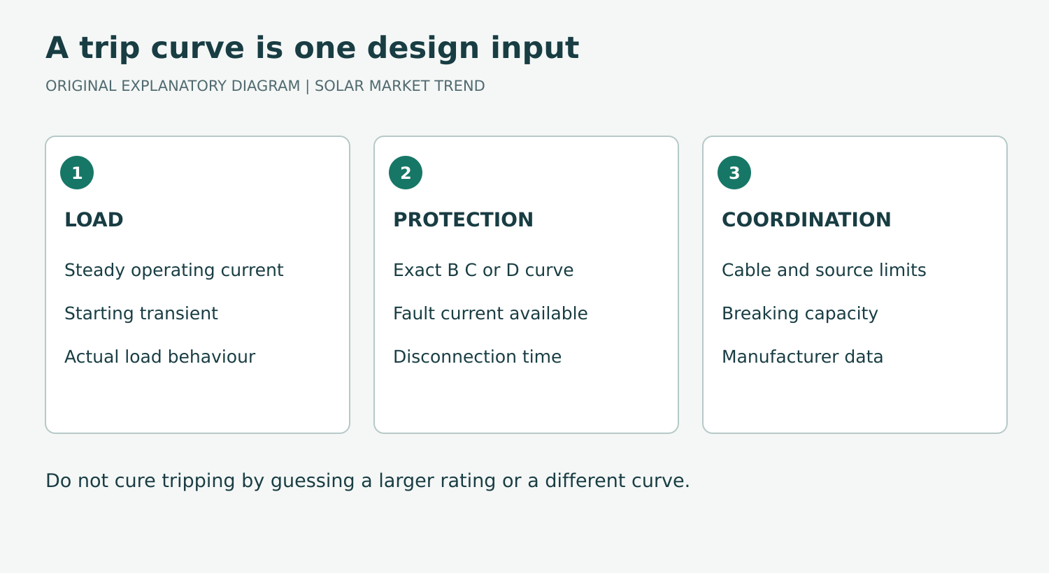
Before accepting a change, request a short written explanation identifying the cause of the original trips, load starting data, exact replacement device, conductor suitability, fault-disconnection verification and any effect on upstream protection. Where a motor starter, drive or equipment fault is involved, changing the distribution breaker may not be the appropriate remedy.
Do not repeatedly reset a circuit with unexplained tripping, defeat protection or increase the current rating as a trial. The correct choice is the one that accommodates legitimate starting behaviour while maintaining verified protection—not simply the breaker that stays on.
Sources and references
- [1] ABB — Electrification Solutions for Industries, UK edition, page 9: S200/S200M tripping characteristics
Checked 2026-10-23
Primary manufacturer curves distinguish thermal/magnetic regions and list IEC/EN60898 AC B 3–5×In, C 5–10×In, D 10–20×In.
- [2] Schneider Electric — B, C, D, K and Z trip characteristics FAQ
Checked 2026-10-23
Load inrush distinction; IEC60898 versus IEC60947-2 interpretation; listed manufacturer's D/K 10–14×In example is not a universal IEC60947-2 band.
- [3] Schneider Electric Electrical Installation Guide — TN system: High fault current-loop impedance
Checked 2026-10-23
High TN fault-loop impedance may prevent required overcurrent disconnection; lower magnetic thresholds and inrush trade-off.
- [4] ABB — International standard requirements for selectivity
Checked 2026-10-23
Coordination requires considering both protective-device characteristics and combined behaviour; curve letters alone do not establish selectivity.
- [5] Victron Energy — SUN Inverter Manual, Installation, AC output connection
Checked 2026-10-23
Product-specific AC short-circuit current limiter and overload detection; qualified-electrician installation requirement.
- [6] SolarEdge — Determining the Circuit Breaker Size for Commercial Inverters, Version 1.8 (August 2026)
Checked 2026-10-23
Covered commercial products require B or C characteristic; product/model-specific selection, not a universal solar rule.