ELECTRICAL TERMINAL TORQUE GUIDE
Electrical Terminal Torque: Why Tight Enough Is Not a Test
Share on social media
Learn what to request from a solar installer about terminal torque: exact manufacturer instructions, suitable tools, documented workmanship and a maintenance plan that avoids indiscriminate retightening.
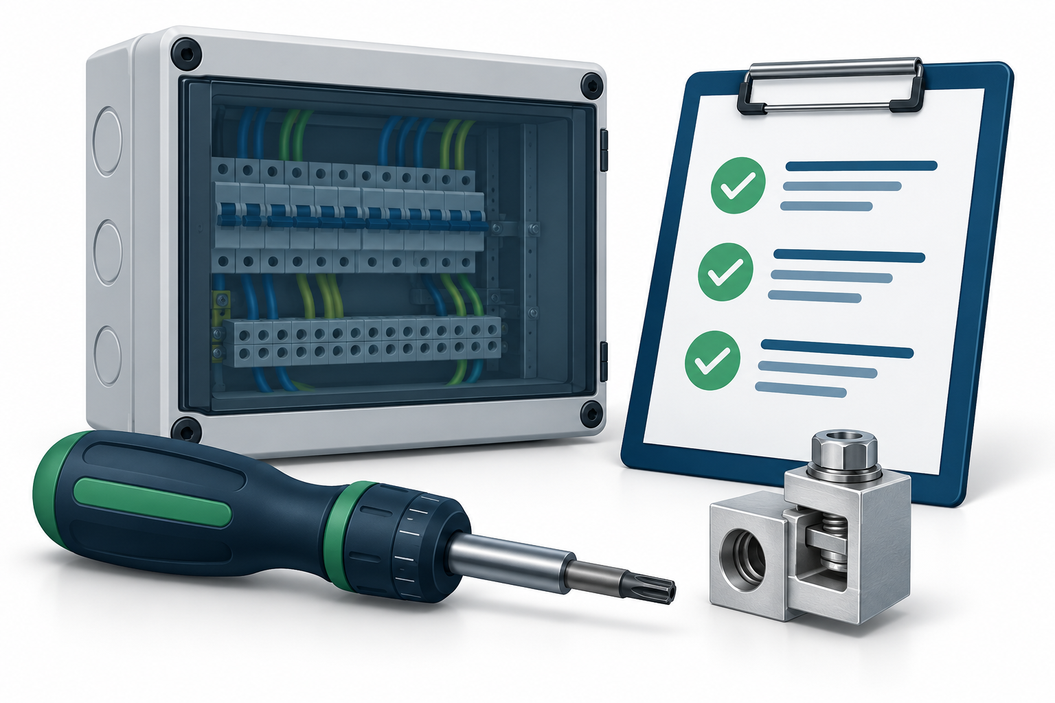
Ask how the connection was verified
At a solar installation handover, 'everything is tight' can sound reassuring. It does not tell the buyer which connection instructions were followed or how the work was checked. A better question is: 'Can you show the specified terminal torque and the commissioning record for this equipment?'
Loose or corroded connections can develop increased resistance and unwanted heating. Fluke's application note discusses thermal investigation of loose, over-tight and corroded electrical connections, showing why simply applying more force is an incomplete response. [1]
For a homeowner or business in Pakistan, the useful role is to request evidence from the installer. Do not open an inverter, distribution board or battery enclosure to judge tightness yourself.
The instruction must match the exact terminal
Torque is the turning effort applied to a fastener. The correct installation value belongs to the particular connection and manufacturer instructions, not to 'solar wiring' as a general category. Even one assembly can contain different types of fastening points.
Phoenix Contact's AK 4 terminal data includes a defined tightening range, screw type, stripping length and separate permitted conductor cross-sections. Its MPT 0,5 PCB terminal has a different torque range and an additional application note about supporting the component during connection. [2][3]
These examples illustrate why copying one number across a cabinet is poor practice. Ask the installer to identify the exact terminal or equipment model and applicable instruction revision. Values from a different model should not be treated as interchangeable.
A number without its location and unit is incomplete
A torque entry should identify what was tightened as well as the value and unit. A lug-mounting fastener and the screw that clamps a conductor are different connection details; a figure for one should not be assumed to cover the other.
Schneider Electric's guidance for an I-Line HCP panel, for example, answers a specifically scoped question about the nut attaching a main lug to its connector. Its value is expressed in foot-pounds. [4] That instruction is not a general setting for inverter terminals.
Request records that preserve the manufacturer's units clearly. Abbreviations such as N·m, lbf·in and lbf·ft should not be casually shortened to 'pounds' or copied without checking. Buyers need a legible, reviewable record rather than a collection of unexplained numbers.
The tool and its condition belong in the record
A suitable torque screwdriver or wrench helps a qualified installer apply a specified value consistently. Merely owning one does not establish that the correct setting, working range or procedure was used. Ask what tool was used and how its accuracy is managed.
Wera describes torque tools with defined measuring ranges and procedures for checking adjusted settings using torque-test equipment. Eaton's instructions for one switchgear regulator explicitly call for calibrated torque screwdrivers and wrenches. [5][6] Those product examples support asking for controlled tools, not adopting their settings for unrelated equipment.
A practical commissioning sheet can record the terminal reference, required value and unit, instruction source, tool identification, technician and date. This suggested record format makes later queries easier to resolve.
Original companion diagram
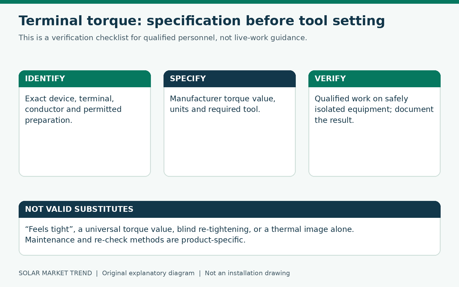
Correct torque does not replace correct assembly
Torque is one part of connection quality. The conductor still needs to match the terminal's permitted type and size, with preparation and any required termination accessories following the manufacturer's instructions. Phoenix Contact's connection data lists these parameters alongside torque rather than presenting torque as the only acceptance criterion. [2][3]
A thermal image can add useful operating-condition evidence, but it cannot reconstruct every installation step or identify an exact tightening value. Fluke stresses comparing similar connections under comparable loads and documenting findings; apparent hot spots require proper investigation. [1]
For a buyer, the sensible request is a combined workmanship review. Do not accept a single thermal photograph as proof that every terminal was assembled correctly, or a torque log as a substitute for the rest of commissioning.
Avoid a blanket retightening instruction
An annual promise to 'retighten every screw' may sound thorough, yet the correct maintenance procedure depends on the equipment. Some connections have explicit instructions against routine retightening after commissioning.
Schneider Electric's FlexSeT switchboard guidance identifies its busbar joints as maintenance-free and says they must not be retightened after the pre-energizing checkout. It instead calls for checks for damage such as corrosion, pitting or heat-related discoloration and gives replacement instructions where needed. [7]
That guidance applies to the named product; it does not establish that all solar terminals are maintenance-free. The broader buying lesson is to ask for a model-specific maintenance plan. Any inspection, adjustment or replacement should follow the relevant manufacturer procedure, rather than a generic schedule copied across unrelated equipment.
Make the handover about evidence, not hand feel
Before accepting the installation, request three things: the connection instructions for the installed models, the completed commissioning evidence, and a maintenance plan identifying who is responsible for professional inspections. Keep these with equipment serial numbers so a later service company can review the original work.
If an installer cannot produce the required connection information, ask for the gap to be resolved through the equipment supplier or manufacturer before acceptance. Do not substitute an internet torque table for missing instructions.
This checklist is for reviewing professional work, not for live testing or DIY tightening. Electrical equipment should be installed and maintained by qualified personnel. [7] The strongest reassurance is a traceable process that follows the exact equipment instructions.
Sources and references
- [1] Fluke: Loose or Corroded Electrical Connections application note
- [2] Phoenix Contact: AK 4 connection terminal block 0404017 technical data
- [3] Phoenix Contact: MPT 0,5/2-2,54 PCB terminal block 1725656 technical data
- [4] Schneider Electric: I-Line HCP main-lug mounting torque FAQ
- [5] Wera: 7400 series factory-preset torque screwdrivers
- [6] Eaton Crouse-Hinds: Document 1222 PRO Power Switchgear Regulator Instruction Manual
- [7] Schneider Electric: FlexSeT busbar joints, lug terminations and insulating-material maintenance