SOLAR DC CABLE BUYER GUIDE
Solar DC Cable Sizing: Why Current Rating and Voltage Drop Are Different Checks
Share on social media
A solar cable must carry the design current safely and limit voltage drop under the stated conditions. Learn what a buyer should request from the installer.
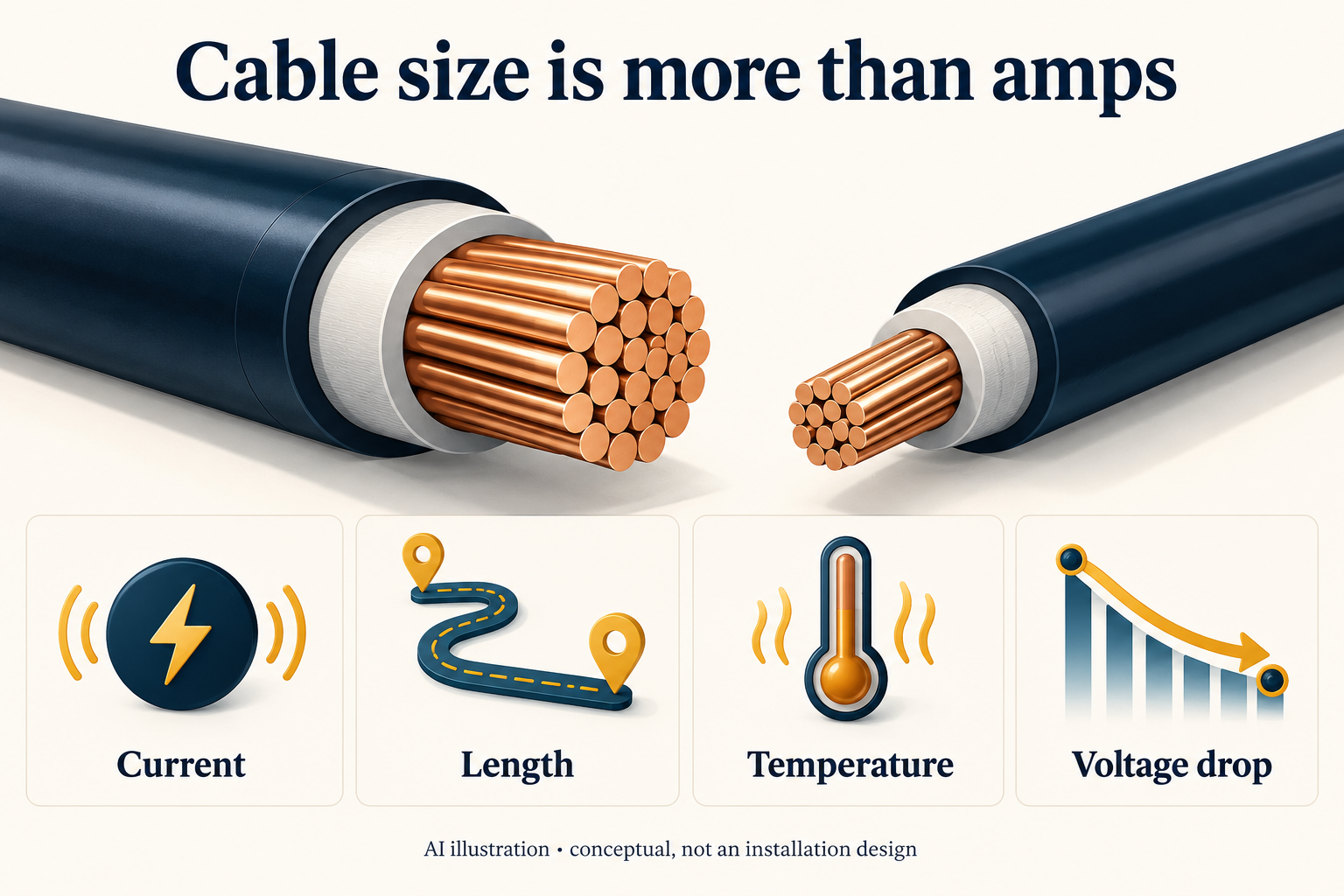
A cable-size label is only the starting point
When comparing solar quotations in Pakistan, a line reading “DC cable included” leaves important questions unanswered. Even a stated cross-section does not show why that cable suits the proposed installation. Ask for a short cable schedule tied to the actual system, rather than accepting a size because another house used it.
Two checks deserve separate explanations: current-carrying capacity under the installation conditions, and voltage drop at the relevant operating current. Passing one does not automatically establish the other. These checks are part of a professional design, not a complete do-it-yourself cable-selection method.
Current capacity depends on the installation
Current-carrying capacity concerns the current a conductor can carry within its thermal limits under specified conditions. Schneider Electric's installation guide explains that reference ratings must be adjusted for the actual service conditions, including ambient temperature and installation method. [1]
PVsyst likewise warns that allowable current depends on heat dissipation, the wire's surroundings and grouping. A software suggestion based on a default installation arrangement still needs verification against the real project. [2]
The buyer's question is simple: “Which rating applies to the way this cable will actually be installed?” A table copied without its temperature and installation assumptions is not a complete answer. Ask the designer to record those assumptions, particularly when quotations use different cable specifications.
Voltage drop is a different calculation
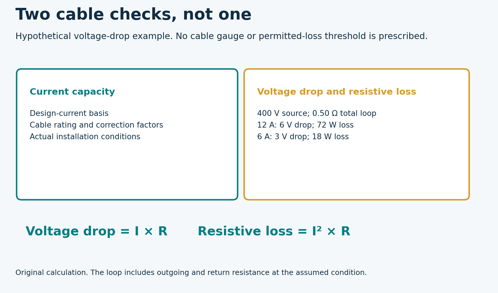
A current flowing through resistance causes a voltage drop and dissipates power as heat. For a simplified steady DC circuit, voltage drop equals current multiplied by resistance; resistive power loss equals current squared multiplied by resistance. The resistance includes the relevant outgoing and return paths, not merely the distance visible on a roof plan. Victron's wiring guide explains these relationships. [3]
Illustrative example: assume a 400 V source, a steady 12 A current and 0.50 ohm total loop resistance at the assumed operating condition. The cable drop is 6 V, or 1.5% of the source voltage. Resistive loss is 72 W. These are hypothetical values, not a cable recommendation or a permitted-loss threshold.
If the same assumed circuit carried 6 A, the drop would be 3 V and loss 18 W. This original comparison shows why an energy-loss estimate depends on the operating current, not only the number of metres of cable.
Original companion diagram
A low loss figure does not prove adequate current capacity
Suppose a quotation provides only a calculated voltage drop. Ask for the separate current-capacity check and the conditions behind it. Conversely, a cable with sufficient current capacity may still have an undesirable voltage drop over a long circuit. The two questions address different aspects of performance.
Specify what the calculation includes. Does the stated length represent one-way distance or the full circuit? Are the current and resistance assumptions clearly identified? A precise-looking percentage is hard to assess if those inputs are missing.
Do not apply the illustrative 1.5% above as a universal target. Ask the qualified designer to explain the project's chosen limit and the equipment or design requirements supporting it.
Read the complete cable datasheet
Manufacturer data can show why a single ampere figure is insufficient. Prysmian's TECSUN H1Z2Z2-K example datasheet distinguishes current capacity for a single cable in free air from a single cable on a surface, and states the ambient-temperature condition. It also specifies conductor resistance, DC voltage rating and environmental test standards. [4]
This is evidence about the information a proper specification can contain, not an endorsement of that product or a statement of Pakistani availability. Ask for equivalent traceable information for the exact cable offered.
A larger cross-section alone does not answer every question about suitability. Request confirmation of the cable's intended PV application and voltage rating, as well as compatibility with the specified equipment connections. Do not substitute a product solely because its outer appearance seems similar.
What to request with the quotation
A useful written cable schedule should identify:
- The circuit being assessed, such as an individual PV string or battery connection.
- The cable manufacturer, model and conductor cross-section.
- The current basis used for selection and the applicable installation conditions.
- The current-capacity assessment after relevant corrections.
- The circuit length, resistance assumption and voltage-drop result.
- The design basis and any changes that would require reassessment.
Keep PV-string and battery-circuit calculations identifiable rather than accepting one generic “DC cable” answer for both. If the equipment location changes or the system is expanded, request an updated schedule before the installation changes are carried out.
Where two proposals differ, ask each installer to explain the reason. The objective is a documented selection, not automatically the thickest or cheapest option.
Check the paperwork, not live conductors
Cable selection and electrical testing belong with qualified personnel. Do not remove insulation, open energized enclosures or probe live DC terminals to validate a quotation. Ask the installer for appropriate commissioning records and keep them with the system documents.
The practical takeaway is to obtain two clearly explained results: adequate current capacity for the real conditions, and an acceptable calculated voltage drop. A cable label without those assumptions is incomplete evidence.