SOLAR EARTHING & BONDING GUIDE
Solar Earthing vs Bonding: Why an Earth Rod Is Not the Whole Safety System
Share on social media
Understand the different jobs of electrodes, protective conductors and bonding, and why a single resistance reading cannot certify an entire solar installation.
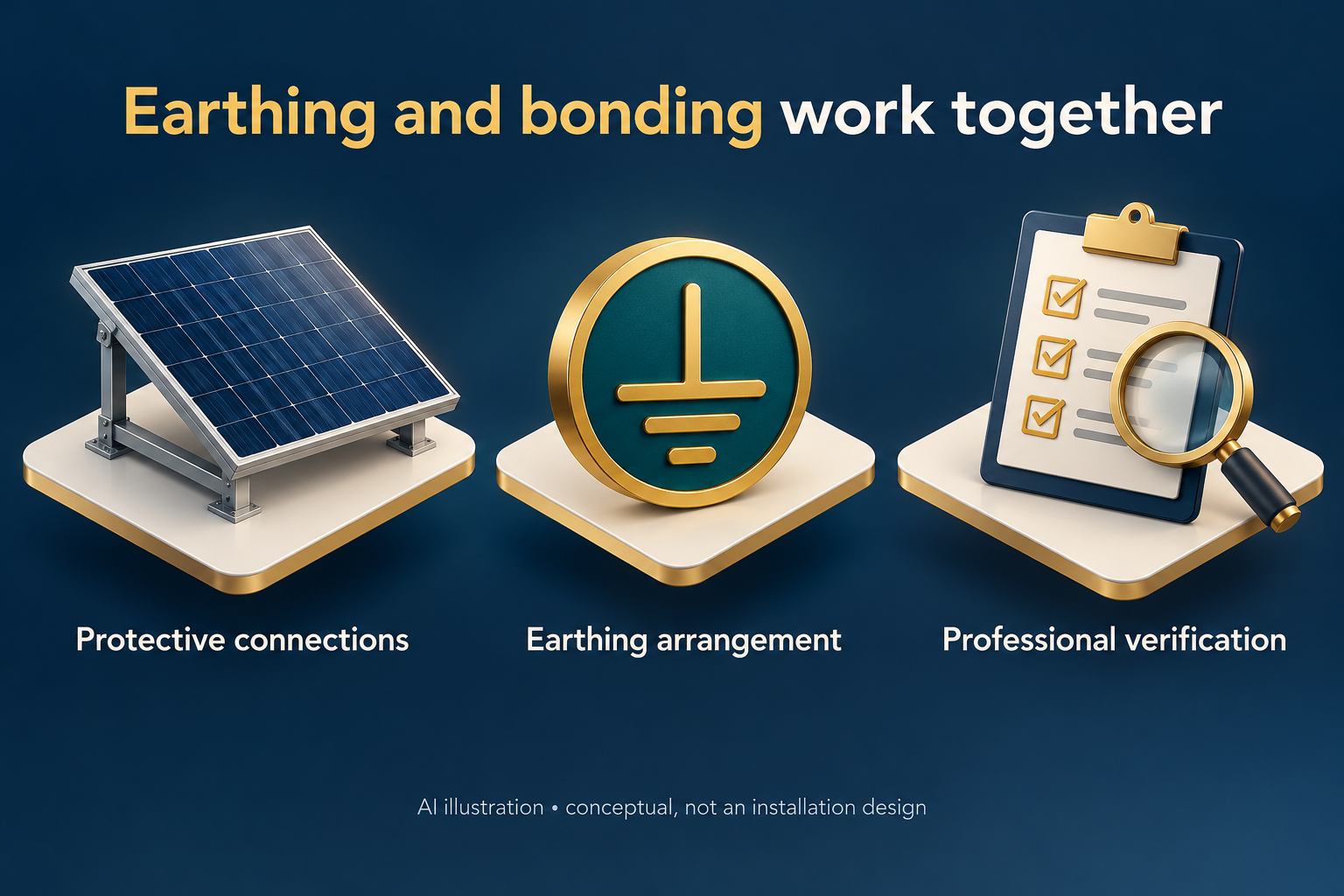
Ask what the earthing line item actually covers
A quotation promising “earthing included” can sound complete while leaving the scope unclear. Does it cover only an electrode, or also the protective connections, equipment requirements and verification of the finished installation?
For a Pakistani homeowner, counting rods is a poor substitute for understanding the documented safety arrangement. The useful questions concern the whole installation: which parts require protective connections, how those connections are provided, and what qualified personnel have verified. This guide explains the terms so you can ask better questions; it is not an installation procedure.
Earthing and bonding have related but different roles
An earth electrode is a conductor in electrical contact with the earth. An earthing conductor connects the installation's main earthing terminal to its means of earthing. Bonding establishes electrical connections between relevant conductive parts to limit potentially dangerous differences in voltage. Schneider Electric's guide distinguishes these components rather than treating them as one interchangeable item. [1]
Protective earthing, often abbreviated PE, concerns protection against electric shock. Exposed metal equipment parts that are not normally live may become energized under a fault. The required protective arrangement must therefore do more than show that a rod exists somewhere near the building. [1][2]
Ask the installer to explain the arrangement in plain language and identify its scope on the system documentation. You should not have to infer it from a photograph of a wire disappearing into the ground.
Continuity matters throughout the protective path
A protective conductor must retain reliable electrical continuity and be protected against deterioration. Schneider's guidance highlights mechanical and chemical damage and explains how a poor connection can leave downstream equipment without the intended protection. [2]
An electrode test does not establish continuity at every equipment connection. Ask for documented verification of both aspects, not just visible wires.
The route of fault current and the method of achieving protection depend on the actual supply and earthing arrangement. Do not accept a generic explanation that all faults simply disappear into the soil. Ask a qualified electrical professional to confirm how the solar equipment fits the building's existing system.
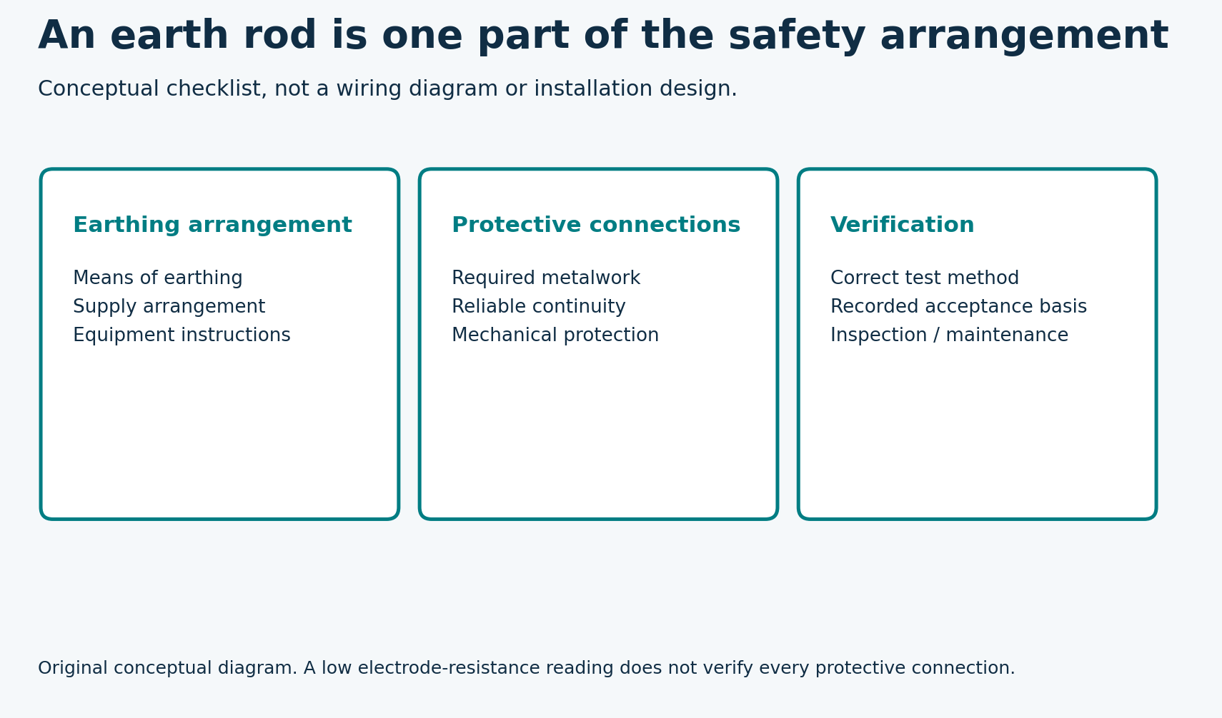
Original companion diagram
Protective bonding is not permission to earth a DC pole
Connecting the appropriate equipment metalwork to a protective system is different from intentionally connecting a live DC pole to earth. Inverter requirements matter. For example, Schneider's Conext CL125 manual requires protective grounding while explicitly prohibiting grounding either positive or negative PV-string poles, because that inverter does not isolate the PV circuit from the grid. [3]
That manufacturer-specific example is included to show the distinction, not to recommend the product or prescribe its arrangement for another inverter. The exact equipment manual and professional design govern the installation.
Do not add a PV-negative, battery-negative or neutral-to-earth link because someone calls it “extra earthing.” Do not remove an existing connection on that basis either. Have the responsible professional identify and verify the intended arrangement, including any relevant operating modes.
What an earth-resistance result does and does not show
An earth-electrode resistance test addresses the electrode's connection with earth. It is not the same question as whether all required protective bonds are continuous. The method also matters: Fluke describes distinct electrode-testing and stakeless loop-testing approaches, with different circuit conditions and interpretations. [4]
A photograph of a low number on a tester is therefore incomplete evidence. Request the test method, what was tested, the date, the result and the acceptance basis used by the competent professional. Do not treat an unlabeled reading as certification of the whole solar installation.
This article gives no universal resistance target. The applicable requirements depend on the actual protective arrangement and design. A figure quoted for another country's example or another type of installation should not be presented as a universal Pakistani solar rule.
Request a useful handover record
Before signing off the work, ask for documentation that answers:
- What supply and earthing arrangement was identified?
- Which solar-system parts require protective earthing or bonding?
- Which manufacturer instructions were followed?
- How were protective-connection continuity and the relevant earthing performance verified?
- What acceptance criteria were used, and who performed the checks?
- What inspection or retesting is recommended for this installation?
Keep the records with the inverter and module model numbers. If equipment is replaced or the installation is extended, ask whether the safety arrangement and verification need updating. An old test result should not silently be treated as evidence about newly added work.
Fluke also notes that corrosion and changing soil conditions can affect an earthing system over time. [4] Ask for a maintenance recommendation rather than assuming a one-time result remains valid indefinitely.
Leave alterations and testing to qualified personnel
Do not disconnect an earth conductor to experiment, open live equipment or deliberately create a fault to test protection. A suspected damaged connection, shock or tingling sensation calls for prompt professional attention, not an improvised extra rod.
The buyer takeaway is straightforward: an earth electrode, protective conductors and bonding perform distinct functions within a designed safety system. Ask for the complete scope and its verification, not just a rod count or a resistance number.