INVERTER BUYER GUIDE
Solar Inverter kW kVA and Power Factor Where Reactive-Power Headroom Goes
Share on social media
An inverter’s active-power rating is not its complete AC capability. Learn how reactive power uses apparent-power headroom and what evidence to request before buying.
One capacity number is not the whole specification
A solar inverter described only as “10 kW” leaves an important purchasing question unanswered: what apparent power can it handle while also supplying or absorbing reactive power? This matters when comparing quotations for a Pakistan home, shop or commercial building. Ask the seller to identify the active-power rating, apparent-power rating and applicable operating conditions separately. Do not assume that kW and kVA are interchangeable, or that a power-factor menu automatically proves the inverter can provide every advertised function at full active output.
Three quantities three different jobs
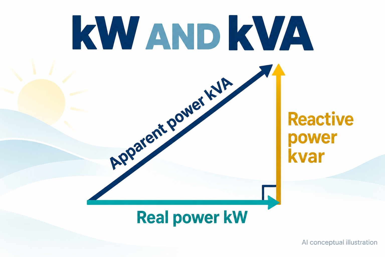
Active power, P, is measured in kilowatts and represents net energy transfer, including useful work and losses. Reactive power, Q, is measured in kvar and describes back-and-forth energy exchange involving electric and magnetic fields. Apparent power, S, is measured in kVA and combines their demands on the AC equipment. It is not found by simply adding kW and kvar. SMA technical explanation
For the simplified sinusoidal case used here, S² = P² + Q² and the displacement power factor is P/S. Consequently, the same apparent-power limit leaves less room for active power when the magnitude of reactive power increases. This illustration does not attempt to model harmonic distortion or every operating limit of a real inverter.
A calculation that exposes the missing headroom
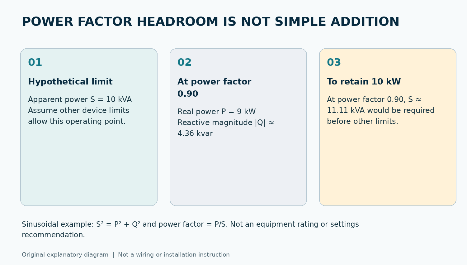
Consider a hypothetical inverter with a 10 kVA apparent-power limit, assuming its other limits permit the operating point. At a power factor of 0.90, the corresponding active power is 10 × 0.90 = 9 kW. The reactive-power magnitude is approximately 4.36 kvar, from √(10² − 9²). The numbers form a right triangle; they are not 9 + 4.36 kVA.
Conversely, supplying 10 kW at 0.90 would require approximately 11.11 kVA before considering other restrictions. These are explanatory calculations, not recommended settings or an equipment selection. SMA’s planning guidance similarly explains that reactive-power provision must be allowed for when sizing apparent-power capacity. SMA reactive-power planning
The real capability envelope is model-specific
The simple triangle is a starting point, not the full product guarantee. An inverter can have separate limits for active output, reactive-power generation and reactive-power absorption. EPRI’s inverter modelling documentation represents these as distinct parameters, including conditions under which reactive capability is available. Its software defaults are not specifications for a product being offered to you. Request the manufacturer’s actual capability information for the exact model and relevant operating mode. EPRI capability-curve documentation
Control priority also matters. EPRI describes reactive-priority operation that reduces watts when necessary to remain within the VA limit, and watt-priority operation that restricts reactive output instead. Which behaviour applies must be established from the installed product and approved control configuration, not inferred from a brochure headline. EPRI smart-inverter functions, section 11
Request evidence without changing grid settings
Ask the commissioning engineer to record the applicable control mode, its source of instruction, the measurement point and the settings revision. An inverter-terminal measurement and a measurement at the site’s grid connection are not automatically equivalent; SMA’s plant-control documentation discusses the influence of intervening equipment. SMA plant-control explanation
For a Pakistan installation, have the responsible engineer confirm the requirements applicable to that connection with the relevant utility. Overseas manufacturer examples are not Pakistani connection rules. Owners should not copy power-factor values from videos, disable reactive-power functions or alter grid-protection settings to chase a larger watt reading.
Make the comparison auditable
A useful quotation states the exact inverter model, rated kW and kVA, reactive capability and the conditions attached to each figure. A useful handover explains the configured behaviour and retains the supporting documents. Treat unexplained differences between those numbers as a question for the designer, not proof of a faulty inverter. The buying goal is enough documented capability for the agreed application, not the largest isolated number on the page.
Sources and references
- [1] SMA — Integrated Plant Control and Q on Demand 24/7, version 1.7
Checked 2026-10-25
Inspected official 13-page technical PDF on 2026-10-25, sections 2 and 3 (printed pp.2–6) for definitions, geometric apparent-power relationship and connection-point considerations. Product/firmware table is model-specific; no universal settings or Pakistan regulatory claims inferred.
- [2] SMA — Why reactive power matters and how SMA technology supports grid stability
Checked 2026-10-25
Inspected full manufacturer page, especially Planning with reactive power, on 2026-10-25. Used for capacity/headroom principle only; German grid requirements and market statements deliberately excluded.
- [3] EPRI OpenDSS — Inverter Capability Curve
Checked 2026-10-25
Inspected complete EPRI documentation on 2026-10-25; separate active, apparent and generating/absorbing reactive limits. Article explicitly warns that model defaults are not hardware specifications.
- [4] EPRI — Common Functions for Smart Inverters, 4th Edition
Checked 2026-10-25
Inspected original 170-page EPRI technical update, dated December 2016, sections 11 and 25 on 2026-10-25; reactive versus watt precedence and VA coupling. Used as technical explanation, not current grid-code authority. Hypothetical arithmetic independently checked: 10×0.9=9; sqrt(100−81)=4.3589; 10/0.9=11.1111.