SOLAR PANEL BUYER GUIDE
Solar Panel EL Testing: What an Electroluminescence Image Can and Cannot Prove
Share on social media
How Pakistan solar buyers can use EL evidence intelligently, distinguish observations from conclusions, and request a traceable inspection report.
Original companion diagram
A useful image needs a useful explanation
When a solar seller sends a glowing black-and-white panel image, the natural question is whether it proves the panel is good. Electroluminescence, usually shortened to EL, is valuable inspection evidence, but the image needs identification, test conditions and interpretation. For a buyer in Pakistan, the useful purchase decision is not simply whether a seller offers EL testing. It is whether the report answers a defined question about the actual modules being delivered.
What the test is doing
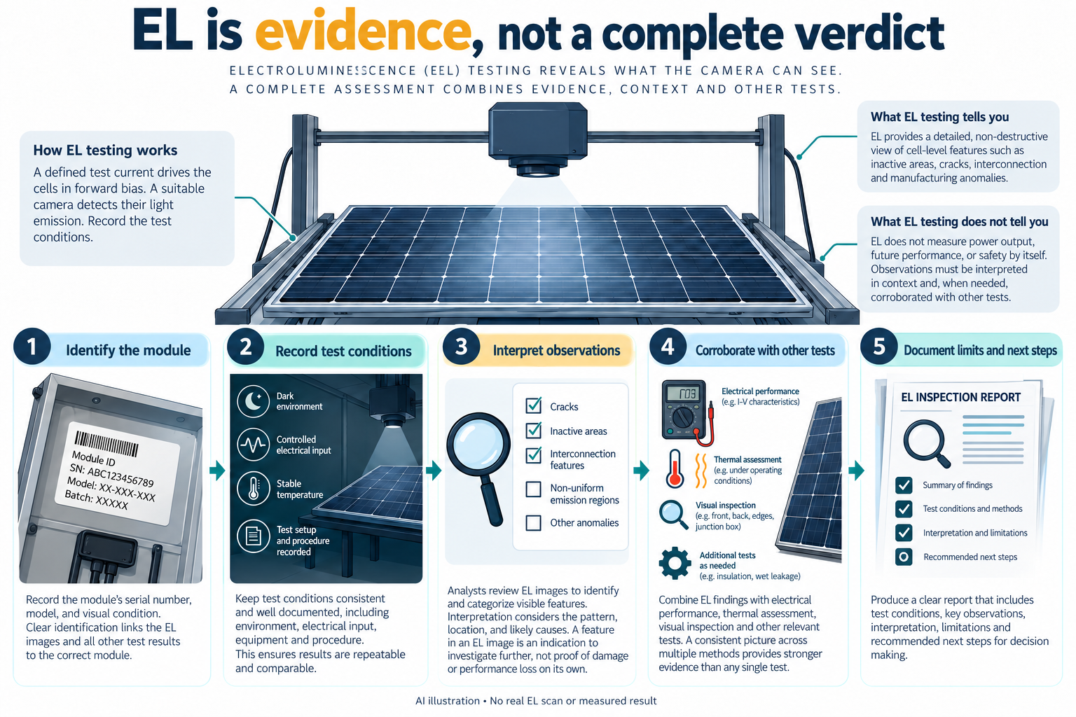
During EL testing, an external power supply drives the solar cells in forward bias. A suitable camera records the resulting light emission. Fraunhofer IEE describes the method as non-destructive optical inspection using a defined test current and near-infrared detection. Differences in the image can reveal cracks or interrupted connections that ordinary photographs do not clearly show. EL is therefore a diagnostic image of electrical behaviour under the test conditions, rather than a normal photograph of the panel surface. [1]
IEC TS 60904-13:2018 covers capturing EL images, processing them into quantitative image metrics and guidance for qualitative interpretation. Its published scope is a measurement-method description. A seller invoking that document should explain what procedure was followed and what acceptance criteria were agreed, rather than presenting the standard’s name as a universal quality grade. [2]
What an EL image can reveal
A research paper by Fraunhofer CSP and collaborators groups EL observations into single cracks, multiple cracks, electrical-circuit anomalies and miscellaneous features. That vocabulary is useful because a dark line, a dark cell and a broad dim region do not necessarily share one cause. The researchers also distinguish an observation from a defect: some visible features originate in normal manufacturing characteristics and do not automatically imply accelerated degradation. [3]
Ask the inspector to mark each relevant cell and describe the observation before assigning a severity. A report that says where a feature is, how confidently it was identified and what further check is needed is more useful than an unexplained red circle. This also makes later comparisons easier when the panel is inspected again.
What it cannot establish on its own
EL alone does not directly certify the panel’s rated wattage, predict its remaining life, or settle who caused damage. The Fraunhofer-led paper notes that cracks can arise during production, transport, installation or operation, and that final conclusions often need flash testing and infrared thermography. It also identifies uncertainty in predicting the power consequences of particular crack patterns, especially as cell and interconnection designs change. Treating every visible crack as an identical percentage loss is not justified. [3]
Power measurement and safety assessment are separate jobs. Fraunhofer CSP lists power measurement, EL, thermography and insulation testing as distinct characterization methods. Depending on the question, an assessor may need several of them: measured electrical output for a wattage concern, thermal evidence for suspected heating, or appropriate electrical-safety tests for an insulation concern. A reassuring EL image should not be used to waive a different necessary test. [4]
Image quality and test settings change the evidence
The IEA-PVPS field-imaging report explains why focus, resolution, noise, stray light and test conditions matter. Darkened conditions help obtain useful signal, while specialised systems can operate under other conditions. It also cautions that one image at one forward-bias current and temperature may not identify a physical mechanism; measurements at different currents and complementary techniques can clarify the finding. [5]
Consequently, two images with different brightness are not automatically evidence that one panel is worse. Before comparing them, ask whether the current, temperature, camera settings and processing were comparable. Request the original full-resolution files, not only a compressed screenshot or a cropped cell that removes the module’s identity. These are practical buyer checks, not a claim that one image format alone determines compliance.
Ask for a traceable report before making a decision
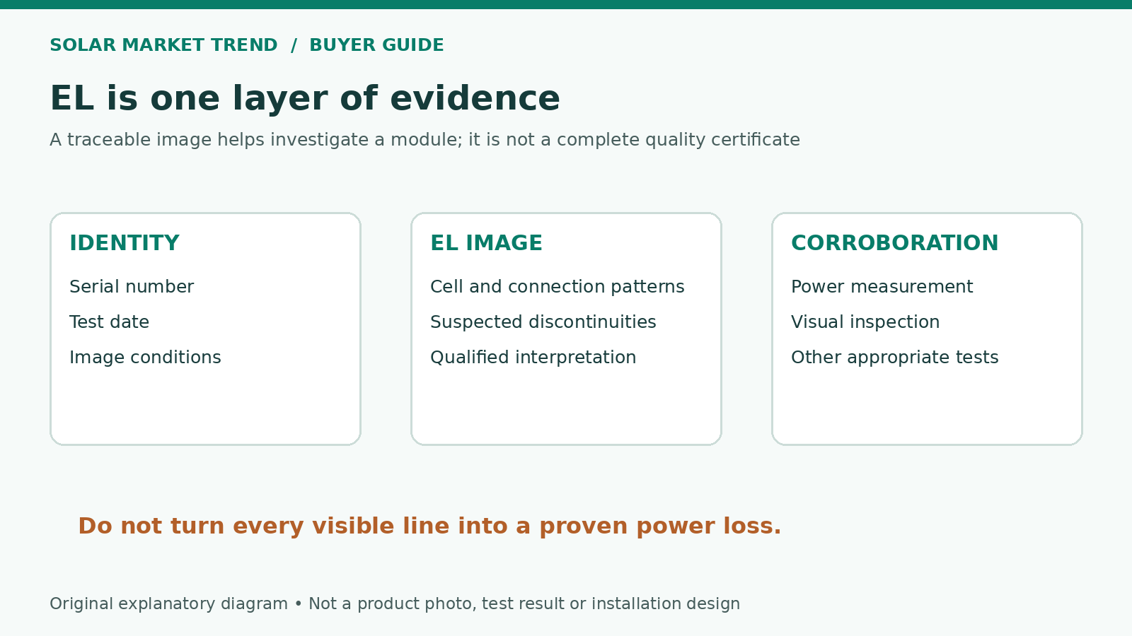
A sensible inspection brief identifies the model and serial number, test date, testing stage, operator, equipment, current settings, available temperature information and any image-processing steps. It includes an annotated full-module image, a clear orientation reference, the observations, limitations and recommended next test. Ask for the acceptance rules in writing before testing begins, including how uncertain or borderline findings will be handled. This is a purchasing checklist, not a substitute for the testing standard.
If only some modules were inspected, the report should identify the sample and how it was selected. A clean image from one panel cannot establish the condition of every panel on a pallet. Likewise, factory evidence documents an earlier stage; useful delivery and post-installation comparisons need traceable images of the same modules, with intervening handling recorded.
Use qualified personnel for testing and installed-system electrical work. The best outcome is a documented decision: accept against agreed criteria, investigate an anomaly, or pursue a supported remedy. EL earns its value by making that decision better informed, not by turning a single picture into a lifetime guarantee.
Sources and references
- [1] Fraunhofer IEE: Photovoltaik-Systeme, Electroluminescence and I-V measurement sections
- [2] IEC TS 60904-13:2018: Photovoltaic devices, Part 13, Electroluminescence of photovoltaic modules
- [3] Jaeckel et al., 2024: Nomenclature and description of Electro-Luminescence observations: cell cracks and other observations
- [4] Fraunhofer CSP: PV Module and Component Characterization
- [5] IEA-PVPS T13-10:2018: Review on Infrared and Electroluminescence Imaging for PV Field Applications