SOLAR PANEL MOUNTING CLAMPS GUIDE
Solar Panel Mounting Clamps Why Position and Hardware Must Match
Share on social media
A clamp that grips the frame is not necessarily approved for the module and rail. Learn which drawings, dimensions and records to request before accepting a solar mounting arrangement in Pakistan.
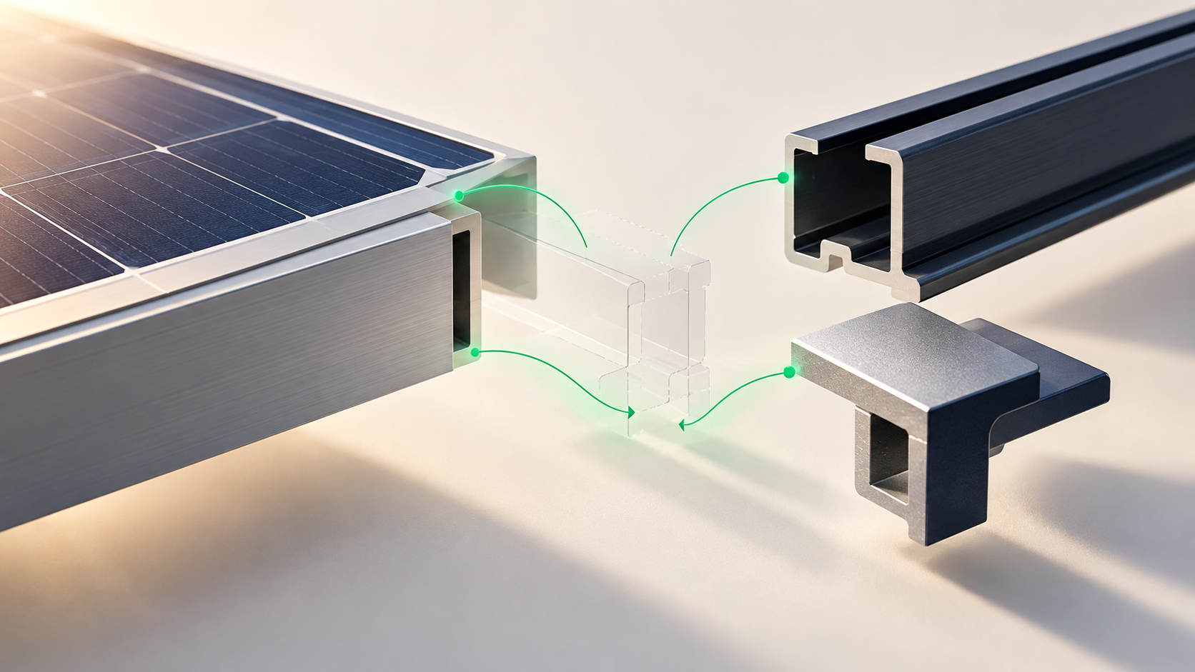
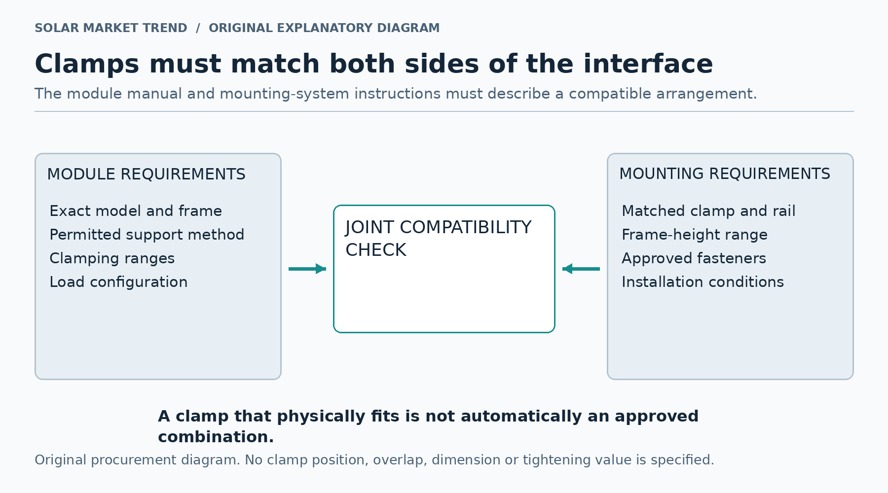
A clamp is part of a matched assembly
A quotation may describe mounting hardware as “standard clamps and rails” while carefully naming every panel and inverter. That leaves an important purchasing question unanswered: which exact clamps, rail profile and module configuration are being supplied?
A clamp is not approved merely because it can be tightened around a frame. Canadian Solar’s installation manual requires authorized clamp positions and warns about clamps that do not match the module’s frame height. [1] For a Pakistani buyer, the practical goal is a documented match between the delivered module and its supporting hardware, not a visual impression that the array looks straight.
Find the exact module row and configuration
Begin with the complete module identification, including the relevant suffix and frame variant. Then ask the installer to identify the applicable manual revision and drawing. “Same brand” and “same wattage” do not identify a mounting configuration.
Trina’s Vertex manual separates mounting arrangements by module type, rail direction, clamped sides and permitted positions. Its drawings also specify which reference point a distance describes. [2] A dimension from one diagram cannot safely be transferred to another arrangement simply because both modules have a rectangular frame.
Our review recommendation is to keep one annotated drawing for the proposed arrangement. It should show which edges are clamped, rail orientation, the specified position range and the reference used to measure it. That is more useful than a photograph of a ruler with no identified drawing.
The allowed zone is not a universal fraction
A clamp-zone drawing identifies where the manufacturer has permitted the frame to be supported for a particular configuration. Canadian Solar’s specified positions refer to clamp centre lines. [1] Do not replace those ranges with a remembered rule such as “one-quarter of the way along every panel”.
This guide intentionally gives no universal millimetre distance. The installer must reconcile the chosen mounting arrangement with the project design; moving clamps to suit an already fixed rail layout is not automatically an acceptable adjustment. If roof geometry prevents compliance, request a revised design or relevant written technical acceptance before the work is treated as finished. A tidy alignment does not resolve an undocumented deviation.
Match the clamp to both frame and rail
K2’s current catalogue provides a useful example of the limits of the word “universal”. Its K2 Clamp Middle Clamp 25-40, product 2004146, is described for a frame-height range but is expressly not compatible with the K2 Dome 6 system. The same catalogue lists separate Dome-system clamps. [3] This is an example of product-specific compatibility, not a recommendation for a particular Pakistani installation.
Ask for the clamp part number, intended frame-height range and compatible rail system. Check the end-clamp and intermediate-clamp applications separately. A component fitting one side of the joint does not establish that its rail engagement and other interfaces are suitable. Where mixed-manufacturer hardware is proposed, the installer should provide the basis for that combination rather than treating interchangeability as obvious.
Minimum dimensions do not prove every alternative
JinkoSolar’s cited manual cautions that its minimum clamp dimensions do not guarantee compatibility with every clamp variation in the market. It calls for alternatives to meet the necessary performance requirements without compromising the installation. [4] This matters when a supplier offers an apparently similar replacement with no identified technical documentation.
Trina’s manual separately addresses clamp contact, deformation, corrosion and keeping clamps away from the front glass; it also prohibits modifying the module frame. [2] These are reminders that the joint is more than a bolt and a nominal width. The article is not a repair procedure: do not drill, file, bend or add improvised packing to make mismatched components fit. Have the responsible installer resolve the incompatibility using documented components and instructions.
Inspect against records rather than appearance
Before acceptance, request the approved hardware list and the applicable module and mounting-system instructions. Have qualified personnel document the actual clamp positions, frame engagement and rail arrangement with clear photographs and measurements. The buyer does not need to climb onto the roof to do this.
A useful handover record identifies who checked the installation, when it was checked and which drawing and document revision were used. Record deviations and how they were resolved. Tightening verification belongs in that professional record, using the applicable product instructions, not a generic value from an online article. JinkoSolar also directs readers to the installer or bracket supplier for the specific fastening requirement. [4] This review should complement, not replace, the structural and electrical commissioning work.
What to do when the specified panel changes
Consider a hypothetical last-minute substitution: the installer replaces the specified module with another product of similar wattage while keeping the original rail and clamp order. That is a change requiring review, not proof of a defect and not automatic permission to proceed.
Ask whether the replacement has the same relevant frame geometry, an applicable mounting arrangement and compatible hardware. Request an updated drawing and revised component list where necessary. If the answer is only that the clamp “looks the same”, the evidence is incomplete. The same principle applies during future panel replacement: keep the original installation records so the new component can be checked against them.
The decision is straightforward: accept a documented assembly, not an unidentified collection of parts. Correct component identity and placement are evidence the buyer can request without attempting installation work.
Sources and references
- [1] Canadian Solar photovoltaic module installation manual
EN-Rev IM/GN-EN/3.1 November 2025 section 6.2 · Checked 2026-10-22
Authorized clamp positions and centre-line ranges; mounting-supplier guidance; frame-height mismatch warning.
Model- and configuration-specific manual, professional use only. No clamp distances or loads generalized to other modules.
- [2] Trina Solar Vertex series user manual
UM-M-0002 Version M February 2025 sections 6.1 and 6.2.2 · Checked 2026-10-22
Distinct arrangements for module types rail orientation and clamped sides; clamp integrity and glass contact; frame modifications prohibited.
Applies to listed Vertex modules only; not asserted to be the newest manual for every currently sold model. Exact applicable revision must be confirmed at installation.
- [3] K2 Systems module clamps catalogue
Current product catalogue checked 22 October 2026 · Checked 2026-10-22
Product2004146 has frame-height range and explicit Dome6 incompatibility; separate Dome clamps show system-specific selection.
Manufacturer catalogue, not approval for a specific installation or Pakistan stock evidence.
- [4] JinkoSolar Global installation manual
A1 file dated 14 August 2024 section 4.2 pages 10–11 printed · Checked 2026-10-22
Minimum clamp dimensions not a guarantee of compatibility with all variants; alternative performance assessment; exact fastening specification to be confirmed with installer or bracket supplier.
Older publicly hosted manufacturer manual used only for the stated general compatibility caution and professional verification principle; not installation authority for an unlisted model.