SOLAR DESIGN GUIDE
Solar Panel and Inverter Compatibility: Check MPPT Voltage and Current
Share on social media
A solar expansion can look sensible on a quotation: add panels, increase the array's kilowatts and keep the existing inverter. The important question is whether the proposed strings stay within that inverter's electrical limits throughout the year.
For a Pakistani homeowner, a useful compatibility check should cover the installation's coldest conditions, hot rooftop operation and the exact arrangement of panels on each MPPT. The following calculations are deliberately hypothetical. They explain the checks to request from a qualified designer; they are not an approved wiring plan or specifications for any product.
Start with the exact model numbers
Ask for the panel datasheet, inverter datasheet and a drawing showing how many modules connect to each input. Record these separate values:
- Panel open-circuit voltage, Voc, and maximum-power voltage, Vmp
- Panel operating current, Imp, and short-circuit current, Isc
- Voltage temperature coefficients and maximum module system voltage
- Inverter maximum DC voltage, start-up voltage and MPPT operating range
- Maximum operating current and short-circuit current for each relevant input or tracker
- Permitted array power and number of independent MPPTs
A connector count does not establish the number of independently controlled trackers. Use the model's connection diagram. SMA explains that independently tracked inputs allow different parts of an array to operate at their own maximum-power points. SMA's inverter-planning guide provides the underlying distinction.
Check cold-weather open-circuit voltage
Series-connected panel voltages add. As a crystalline-silicon module becomes colder, its open-circuit voltage normally increases. Canadian Solar's installation manual describes correcting Voc for the lowest expected site temperature using the module's temperature coefficient. Follow the manual for your exact model. Canadian Solar installation manual
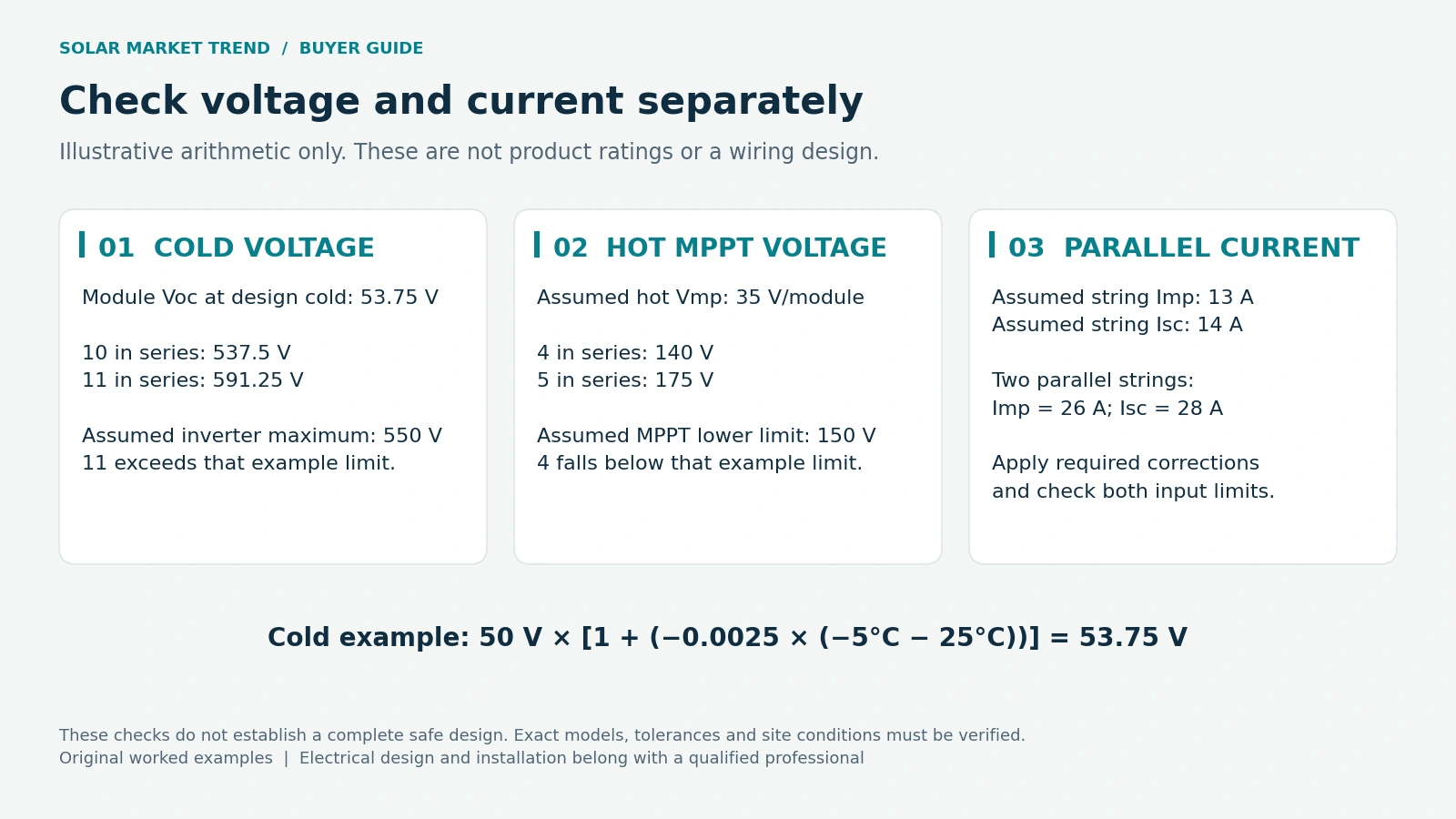
For an illustrative module with Voc of 50 V at 25°C and a Voc coefficient of -0.25% per °C, assume the designer selects -5°C as the minimum design temperature:
Cold Voc = 50 × [1 + (-0.0025 × (-5 - 25))] = 53.75 V
The percentage coefficient becomes -0.0025 in the equation. Ten modules in series would produce an estimated cold open-circuit voltage of 537.5 V. Eleven would produce 591.25 V.
If the hypothetical inverter's absolute DC limit were 550 V, eleven modules would fail this check. Ten would pass only this preliminary voltage comparison. Applicable design allowances, actual site conditions and all other component limits still need checking. Never choose the design temperature from today's weather forecast.
Check the lower voltage limit on a hot roof
Passing the maximum-voltage check leaves another question: will the string's working voltage remain within the MPPT range when the modules are hot?
SMA's PV-generator planning guidance calculates the minimum string length from the inverter's minimum MPP voltage and the module's minimum expected working voltage. Falling below that range can reduce useful tracking. SMA PV-generator planning guidelines
Suppose a designer calculates a hot-condition Vmp of 35 V per module and the example inverter requires at least 150 V for MPPT operation. Four modules give 140 V; five give 175 V. Five clears that illustrative lower threshold. The designer must also check the upper MPPT limit, start-up requirements and any narrower voltage range needed for full output.
Use module temperature for the hot-condition calculation. An air-temperature forecast alone is not a complete rooftop thermal assessment.
Check current separately from voltage
Adding modules in series raises string voltage; placing strings in parallel adds their currents. Two hypothetical identical strings, each with Imp of 13 A and Isc of 14 A, therefore total 26 A operating current and 28 A short-circuit current before relevant design corrections.
Compare the appropriate totals against the inverter's documented per-input and per-MPPT limits. Do not assume that the current allowance of one tracker can be borrowed by another. SMA's module-input requirements separately identify the open-circuit-voltage and short-circuit-current limits. SMA input requirements
Operating-current clipping and a short-circuit-current limit have different implications. SMA permits excess array MPP current for specified models while requiring the short-circuit limit to be respected. Any such allowance must be confirmed for your exact inverter. SMA manufacturer declaration
Ask how enhanced irradiance and bifacial gain affect the calculation. Trina's module guidance identifies irradiance and rear-side conditions among the design factors. Trina installation guidance An acceptable array wattage does not settle these checks.
What about mixed panels and roof directions?
Different panel models, string lengths or roof orientations need an explicit design review. SMA specifies matching modules and string arrangements for the inputs covered by its manual. Separate MPPTs may help accommodate different roof sections, subject to that inverter's instructions.
Before approving an expansion, request one signed calculation sheet listing cold Voc, hot Vmp, input currents, panel counts and tracker assignments. Keep it with the equipment datasheets. This gives you a clear basis for checking the proposal before anyone changes the roof wiring.
Editorial note: AI-assisted, source-checked buyer guidance. Sources checked 14 October 2026.
Sources
- SMA: PV Inverters, Basic Facts for Planning PV Systems
- Canadian Solar: Installation Manual of Standard Solar Modules
- SMA: Planning of a PV Generator, DC-PL-en-11
- SMA: Requirements for the PV Modules per Input
- SMA: Manufacturer Declaration, MPP Current of the PV Array
- Trina Solar: Vertex Series Module User Manual